Technical
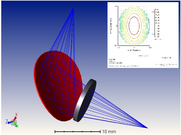
Optical design
We use OpticStudio (also known as Zemax) and SolidWorks for our optical and mechanical design work. Both are industry standards making the sharing of files as trouble-free as possible. Some optical designs will be confidential, but it is possible to provide a Zemax ‘Black Box’ file where appropriate.
Once the optics are finalised, SolidWorks is used to design any mechanical housing required or just to design those items of beam delivery that do not require optics. 3D parts, assemblies and manufacturing drawings can all be created.
Despite being armed with up-to-date software, there are times when we fall back on software like Excel to answer “pre-design” questions like “How large does my laser beam need to be to allow the beam waist to be pushed out to 5 metres?” and therefore “What magnification beamexpander do I need?”. The quirky behaviour of laser beams and the fundamental specifications of an optical system can be quickly determined.
We have designed and developed many of our own products over the years, and have also worked as part of both national and international collaborative projects, including the Laser Snake for nuclear decommissioning.
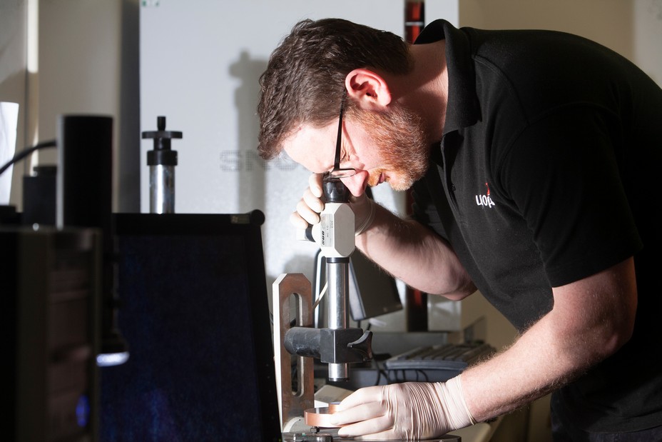
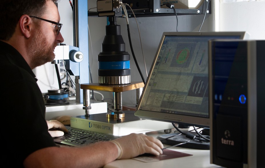
Interferometry
The specifications of most laser mirror surfaces involve sub micrometer dimensions, too small to measure mechanically. Interferometry uses laser light to generate interference patterns that can be interpreted to measure the flatness, radius of curvature, or angle of a laser optic as well as other properties.
For the majority of our mirrors we use a phase shifting interferometer for quality assurance. With software analysis of the interference pattern a hard copy of the results is available to our customers. This demonstrates that surface form specifications such as power and irregularity have been met.
This measurement of the spacing and curvature of the black and white lines (or fringe pattern) can be used to interpret the optical flatness of the laser mirror.
What is it used for?
It is also useful to measure and align optical assemblies such as reflective beam expanders or collimators, with an interferometer.
Of great interest to us has been investigating the mounting of optics and observing the deformation that can occur to mirrors from poorly designed mounts or excessive mechanical force. We can supply mirrors complete with mounts and internal water cooling, proven by interferometry that the assembled mirror has not been deformed.
We also use interferometry to measure the wedge of flat laser mirrors to ensure parallelism.
Results can be reported in many different forms, such as ISO 10110, Zernike polynomials or graphically.
As part of the company’s commitment to innovation and growth we have invested in a new 3D optical profiler (Filmetrics Profilm 3D). It uses state-of-the-art white-light interferometry to enable us to measure surface roughness from sub-nanometer to millimetre scale – something that is essential for some of our customers where surface finish is vitally important. Reports are easily generated and can be supplied upon request by customers.
Laser damage
LBP Optics in partnership with UK and European Universities have investigated the causes of laser damage and measured the Laser Induced Damage Threshold (LIDT) of many CO2 laser optics.
Proc. SPIE Vol. 3244, p. 188-198, Laser-Induced Damage in Optical Materials: 1997, Gregory J. Exarhos; Arthur H. Guenther; Mark R. Kozlowski; M. J. Soileau; Eds.
Proc. SPIE Vol. 2714, p. 281-281, 27th Annual Boulder Damage Symposium: Laser-Induced Damage in Optical Materials: 1995, Harold E. Bennett; Arthur H. Guenther; Mark R. Kozlowski; Brian E. Newnam; M. J. Soileau; Eds.
Laser damage threshold
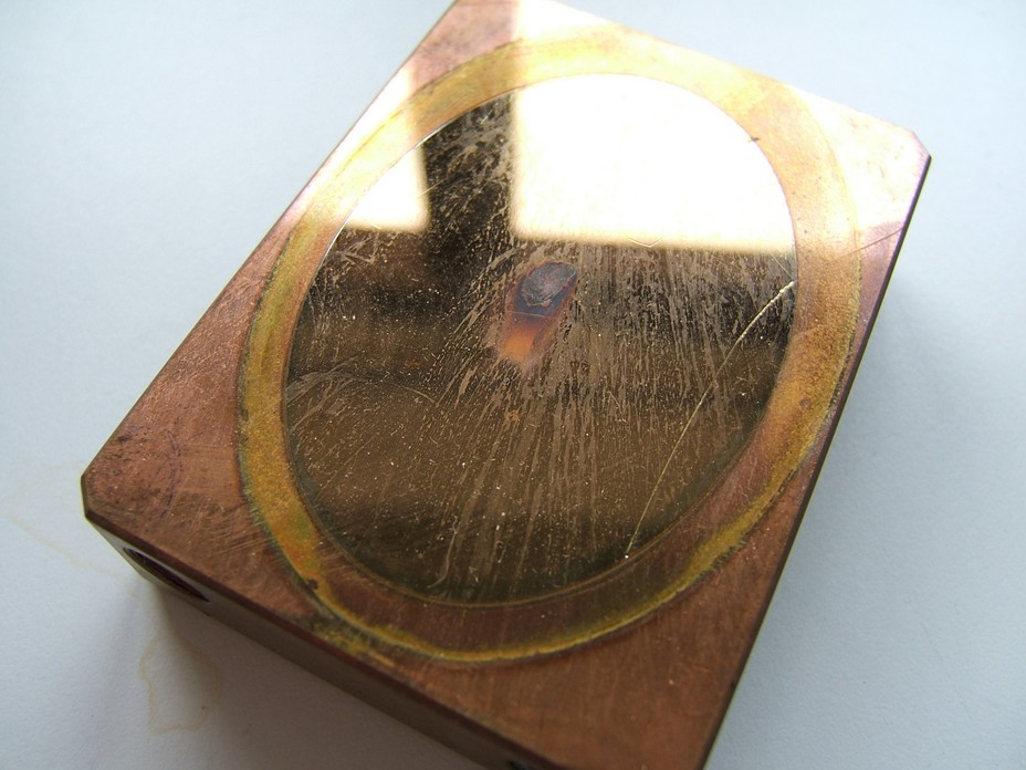
The most important result from this investigation is that copper based mirrors and ZnSe lenses in a typical industrial laser operate at a fraction of their Laser Damage Threshold.
The reason(s) optics fail is entirely due to external factors, e.g. from their operating environment.
In particular, mechanical forces from mounting, clamping etc. significantly reduce the lifetimes of ZnSe lenses. Increased absorption from external contamination or poor cleaning can quickly lead to laser damage. The difference between a good lens and a poor lens can be an increase in absorption of just 1 part per thousand.
Fortunately, the situation with copper mirrors is more forgiving, as their ability to sink heat is so much better.
Gold coated copper mirrors are used on lasers of 40 KW power. For 3 KW power or higher copper mirrors are the only realistic choice. Such a large power handling ability means that even when damaged or dirty, copper mirrors carry on working in high power industrial laser systems.
For a laser with a 20mm beam diameter gold coated copper mirrors are working at just a fraction of their potential – see the table below.
| Laser Power | 2KW | 4KW | 5KW | 20KW |
|---|---|---|---|---|
| Fraction of Laser Damage Threshold | 2% | 5% | 6% | 25% |
The correct parameter for expressing laser damage threshold of CW CO2 laser optics is the ratio “P/d” where P is the laser power in Watts and d the diameter of the beam in mm. For a gold coated copper mirror the P/d value that damage occurs at is 4000 Watts per mm. So, to cause laser damage to a gold coated copper optic a 4000W laser would have to be focussed to a spot 1mm in diameter on the mirror surface. This law is a “scaling law”, so 8000kW in 2mm diameter has an identical P/d value, i.e. 4000W/mm.
Calorimetry
A CO2 laser of a known and stable power has the test optic placed in its beam path, in our case the test optic is nearly always a mirror. The mirror under test is heated by the small amount of laser power that is absorbed, and the resulting temperature rise is measured. Despite the mirror being thermally isolated as well as practicable, there is always a small amount of heat loss, so the rate of cooling is measured as well.
Calculating absorption
By knowing the laser power, the weight and thermal properties of the test optic, along with the rate of heating/cooling it is possible to calculate the amount of power that the test optic absorbed. For long wavelengths like 10.6um and a metal mirror, any scattering or transmission is ignored so we can say Reflectivity = 1 – Absorption. The rate of heating and cooling of the test mirror is best measured by the slope of the temperature versus time graph of the mirror during testing. This is measured by a thermocouple attached carefully to the mirror, its voltage output recorded by a high speed, high bit rate A-D data logger. A spreadsheet can quickly analyse the thousands of recorded temperature readings and calculate the reflectivity of the mirror. The accuracy of the technique depends on the size and shape of the mirror to be tested as well as the absorption of the mirror. In general, we can measure the reflectivity of a CO2 laser mirror with an accuracy far greater than would ever be needed by customers.
Cleaning
With an imaging system, increasing detector amplification can offset absorption of light by optical elements. With high power systems, however, that absorbed light will lead to heating of the elements and a level of distortion is inevitable as the optic changes shape, or refractive index, with temperature.
In laser processing this can have a positive feedback effect. As optical elements distort, the focussed spot or beam alignment drifts away from the predetermined conditions and process back spatter can increase, causing even more contamination and debris.
All optics from the moment of use, and occasionally in storage, will acquire a level of contamination. A cutting lens close to plastic being cut, will be contaminated with condensates and smoke that are essentially organic in nature, whereas a dental laser system will see contamination that is essentially aqueous, or watery, in its nature.
It is not realistic that a single prescriptive cleaning technique could deal with such diversity. Few optics can be mechanically abraded or soak cleaned, so everyday cleaning is limited to wiping with a solvent and a swab. There are several reasons for doing this:
- The optic is not mechanically damaged by scratching.
- The optic is not chemically damaged by etching or other chemical attack.
- Absorption is lowered (transmission increased) to a suitable level for a lens or window.
- Absorption is lowered (reflectance increased) to a suitable level for a mirror.
Given that physical removal of the debris or contamination by rubbing is not feasible, cleaning is reliant on the solvent dissolving the contamination, allowing the resulting solution to be soaked up and removed by the swab. The essential point here is that the solvent dissolves the contamination, resulting in a solution of dissolved dirt that can be taken away from the optics surface.
Consider an everyday example, washing car bodywork. Rock salt is obviously easily dissolved into water, but no matter how many gallons of water were used, no one would expect it to dissolve even a fleck of tar. However, a drop of paraffin results in complete removal of tar. This shows how successful the approach is of knowing the properties of the contamination, and then choosing the appropriate solvent.
The only restrictions in choosing a solvent are avoiding chemical damage to the optic and its coating, and Health and Safety guidelines. Even the most exotic solvent will cost just a few pence per optic cleaned.
Choosing a solvent
A good rule of thumb is ‘like dissolves like’, although how a solid can be ‘like’ a liquid is not immediately obvious. The answer is to do with electrical field distribution at a molecular level; this is termed ‘polarity’. A better adage would be ‘highly polar liquids dissolve highly polar solids; non-polar liquids dissolve non-polar solids’.
In our car-washing example, salt is highly polar solid, water a highly polar liquid. Tar is non-polar, as is paraffin, thus ideal for its removal. It is sufficient merely to have an “instinct” for the polarity of the contamination to choose a solvent, as there is a broad overlap.
The following table gives a feel for polarities of everyday solids and liquids.
Matching contamination to solvent for cleaning optics
| Solid | Polarity | Liquid |
|---|---|---|
| Salts/water residue | HIGH | Water/Vinegar |
| Salts/water residue | HIGH | Alcohol |
| Light Oil | HIGH | Acetone |
| Light Oil | HIGH | Methyl Ethyl Ketone (MEK) |
| Heavy Oil | HIGH | Ethyl Acetate |
| Heavy Oil | MEDIUM | Trichloromethane (Chloroform) |
| Heavy Oil | MEDIUM | Dichloroethane |
| Light Grease | MEDIUM | Trichloroethane ‘TRIKE’ |
| Light Grease | MEDIUM | Xylene |
| Heavy Grease | MEDIUM | Toluene |
| Heavy Grease | MEDIUM | Hexane |
| Tar, Fat, Plastic Residue | LOW | Octane |
All these solvents should be readily available, but the user should check with the optics supplier for compatibility, and be aware of Health and Safety issues.
Even if you are lucky in choosing just the right solvent, it is likely to dissolve just a fraction of its weight in solids. So, several repeated applications will be needed to effectively remove a high proportion of the contamination. At no time is mechanical pressure needed, the solvent does the work, frantic rubbing will not increase its dissolving power in the slightest.
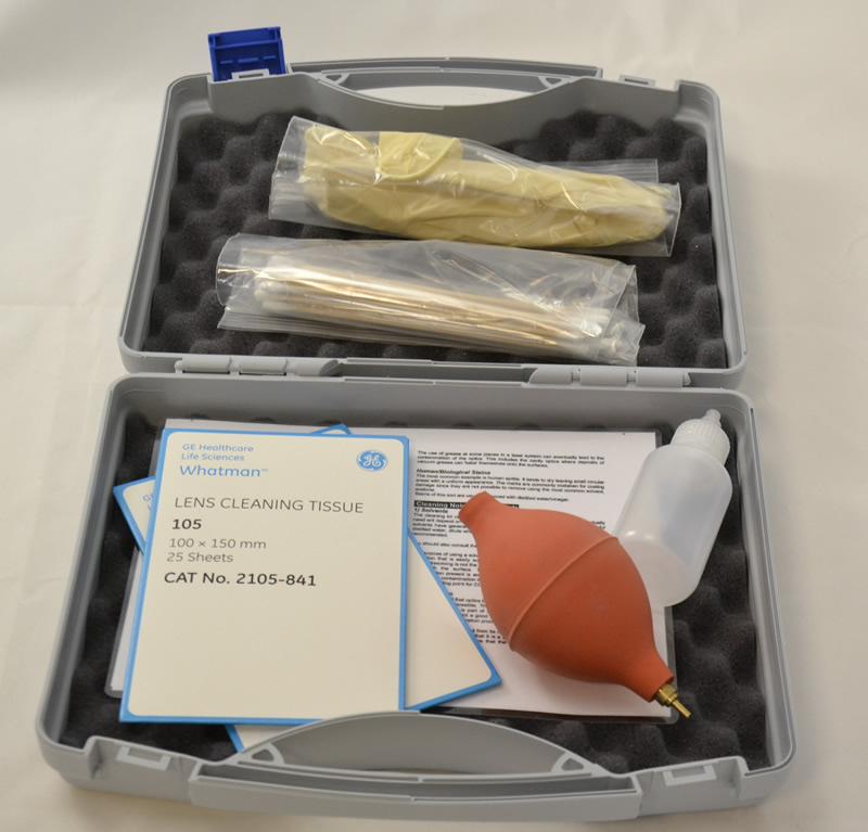
The cleaning process
- We prefer to use a swab such as cotton wool, which will hold a large volume of solvent. Use natural cotton wool, rather than man made mixtures which will cause scratches. The swab needs to be free from all particles, and kept in a sealed bag. Check for seeds and knots before use. The swab should be well wetted, but capable of absorbing a little more liquid. Use a piece at least as large as the optics diameter so only a single wipe is needed for the entire surface.
- Firstly, blow particulate matter off the optic with canned air, all shop air lines contain oil vapour, no matter how well filtered. Don’t forget to check the sides/chamfers and back of the optic where debris can be attached. This can be caught up into the swab and then dragged unobserved across the surface.
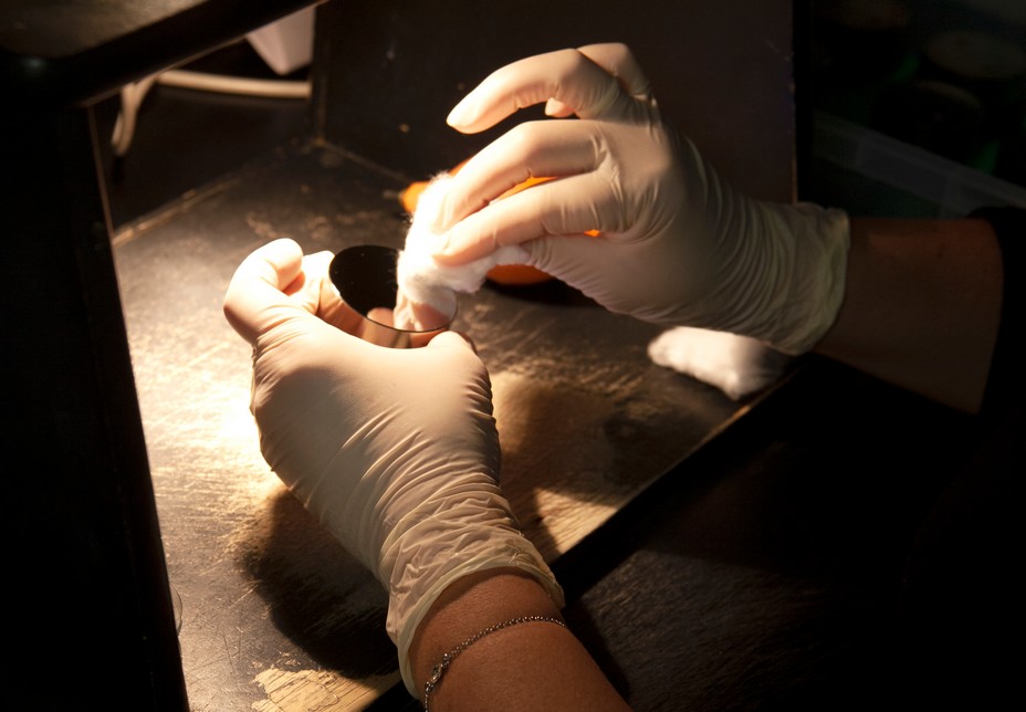
- The solvent soaked swab is dragged slowly across the optic under its own weight ONLY. The solvent at the leading edge will dissolve the dirt and the trailing part of the swab will absorb the resulting solution back off the optic. This should be repeated several times. It is important that the solvent is absorbed back onto the swab and not allowed to dry into a tide mark of concentrated dirt. Change the swab every time, as fresh solvent will dissolve the contamination better. Also, particles picked up in the swab cannot be repeatedly dragged back across the optic.
- Check the optic is clear and free from stains and tide marks. Again, don’t forget the back and sides of the optic or locating holes. These can retain liquid that can later leak out unobserved during mounting or installation.
- If this approach is not familiar, then try a few tests on some “dead” optics first to a get a feel for the technique.
Just how much care in cleaning is needed?
Two questions should be asked when cleaning optics:
- Have I scratched the optic unduly?
- Has the absorption of the optic returned to a low enough level to allow it to function well?
Considering scratching: Optics for high power lasers will be of good quality despite a small number of scratches that appear to be no more, than say, 2- 4 microns wide. With perfect eyesight, and good natural lighting, unskilled examination will easily detect scratches of this level. The absence of scratches when viewed in this way indicates a good quality surface.
If after cleaning the optic passes this test, then well done. There is in general no need for artificial lighting or viewing aids in most situations.
Considering absorption: For high power infrared laser lenses, such as ZnSe, a lens absorbing 0.2% of the beam will generally prove serviceable. Note this is a very small figure, just 2 parts in a thousand. Beyond this thermal effects are likely with very high power systems. A 100-watt system will be one tenth as sensitive as a 1000-watt system, so owners of high power cutting systems need to especially careful.
Metal mirrors are less sensitive, Molybdenum and Copper mirrors for example can often absorb 2.0% of the beam quite happily, ten times that of a lens. Output windows are particularly important, as the laser cavity is sensitive to misalignment and shifting waist locations that occur as the window distorts.
Of the two factors here, low absorption is the more difficult to assess, and achieve. Unfortunately lowering absorption is often the factor that determines the success of cleaning. As an optical manufacturer, LBP Optics can justify the use of sensitive PC based temperature logging; this can measure precisely the amount of a probe laser beam an optic absorbs.