Beam Delivery
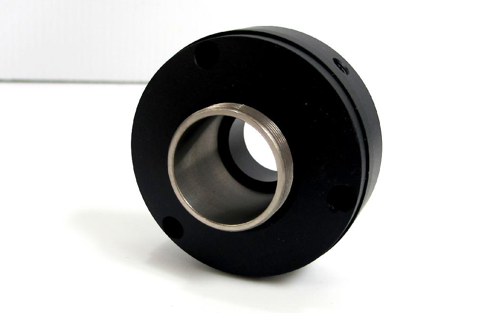
Thread Inserts
Purpose and Functionality
Technical Specifications
- Thread Type: M29 x 1mm
- Inner Diameter: 19mm
The slots strategically placed at each end of these inserts are more than mere design features. They serve a practical purpose: leverage. When tightening against a stop, the slots allow for controlled force application, ensuring a secure fit. Conversely, when it’s time to disassemble, these same slots provide the necessary grip for effortless undoing.
Invisible Strength, Visible Impact
Next time you encounter the COMPACT range, remember that behind its seamless exterior lies the unsung hero—the stainless steel thread insert—quietly ensuring stability, precision, and longevity.
Beam Pipes
Purpose and Functionality
A beam pipe is a critical component in the COMPACT beam delivery system, serving both practical and safety functions. Key aspects include:
Laser Beam Protection: The primary purpose of a beam pipe is to shield the laser beam. By enclosing the beam within a pipe, accidental blockage is prevented. This is especially critical for invisible laser beams, such as the CO2 beam, which must not be obstructed by any part of the body. Safety protocols demand that the beam remains unobstructed for the well-being of operators and personnel.
Beyond safety considerations, the beam pipe contributes to the mechanical stability of the laser assembly. It acts as a rigid structural element that links multiple optical and mechanical components, ensuring positional accuracy and reducing misalignment during operation. This rigidity is crucial when directing the beam from the laser source to the target or through complex optical subsystems.
Purge Atmosphere Management
The beam pipe is also engineered to maintain a controlled purge atmosphere, typically supplied at a slight positive pressure. This serves two critical purposes:
- Particulate Exclusion: The positive pressure prevents the ingress of dust or other airborne contaminants that could degrade beam quality.
- Gas Absorption Control: By minimising the presence of absorbing gases (e.g., atmospheric air), the purge atmosphere stabilises beam propagation characteristics and ensures consistent optical performance.
Technical Specifications
Standard Lengths:
- Beam pipes are commonly available in standard lengths:
- 30mm
- 50mm
- 100mm
- 300mm
- These lengths cater to various applications, from compact setups to more extensive optical paths.
- Beam pipes are commonly available in standard lengths:
Customization Options:
- Longer lengths can be achieved by using thread inserts to connect multiple sections.
- Need an odd length? No problem! An extender pipe allows for customized dimensions beyond the standard options.
- For specific requirements, consider the 30mm length with a purge nozzle (C-BPP30), which combines beam guidance with gas control.
Internal Bore Diameter:
- The internal bore of the beam pipe measures 19mm. This dimension accommodates the laser beam while allowing for easy connection to other components.
- Thread inserts facilitate seamless integration with other optical elements, ensuring efficient beam delivery.
Engineering Elegance
The beam pipe, often overlooked, combines precision, safety, and reliability. Next time you encounter a laser system, appreciate the unassuming hero—the beam pipe—that ensures precise, protected photon flow
Attenuators
Description
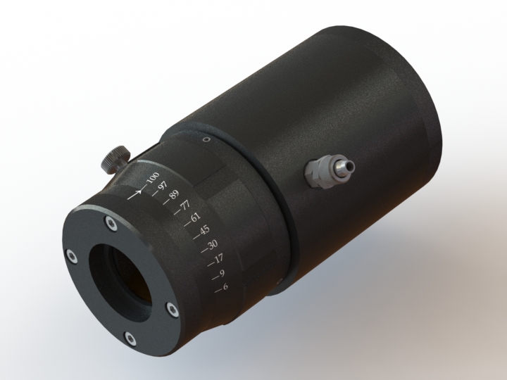
ULO Optics’ Compact 2 manual attenuator allows the user to externally vary the power delivered from the laser.
Many lasers only vary their output power by pulsing full power on and off, and this does not always provide fine levels of control needed in some materials. This device will give infinitely variable control of the transmitted beam from approximately 6% to 100%. An optional manual attenuator with ‘enhanced’ coated Brewster plates provide a transmittance to as low as 0.04% up to 98%.
Technical Specifications
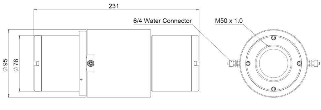
Dimensions: See drawing
Aperture: 38mm
Power rating: ≤1kW
Cooling: Water-cooled, 6/4 connector
Mechanics: Aluminium Alloy, Black Anodised.
Fitting: M50x1.0, female, both ends
Transmission: 6% – 100%, 0.04% – 98%
Optics: Lasergrade ZnSe Brewster Plates
Coating: Enhancing coating available (-E)
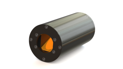
Reflection Isolator
Purpose and Functionality
These optically function in the same way as the attenuators, but do not have the rotatable internal barrel.
The unit is positioned in linearly polarised beam and bodily rotated for maximum transmission and locked in place. The outgoing beam has to be converted to circular polarisation after the reflection isolator. Any reflected power for the target will pass through the circular polariser again and be converted back to linear polarisation. However, the backward beam will be polarised perpendicular to the outgoing beam and therefore dumped by the reflection isolator. In most cases above 100W water-cooling is advised.
Technical Specifications
Dimensions: see drawing
Aperture: 38mm
Power Rating: ≤1kW
Cooling: Water-cooled, 6/4 connector
Mechanics: Aluminium Alloy, Black Anodised
Fitting: M50x1.0, female, both ends
Optics: Lasergrade ZnSe Brewster Plates
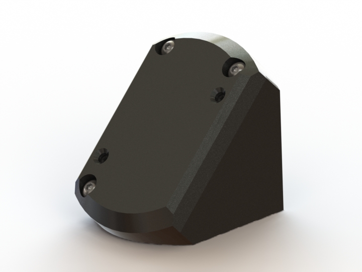
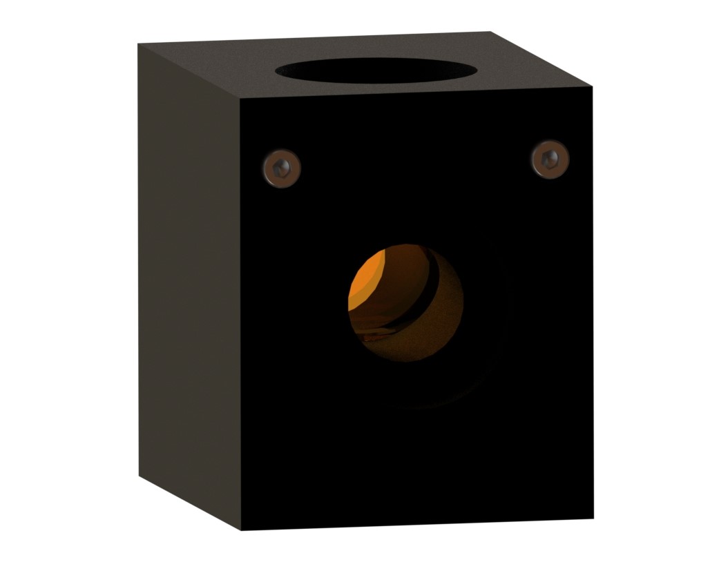
Corner Mirrors
Purpose and Functionality
The C-CM corner mirror block uses Silicon mirrors of 25.4mm (1”) or 25mm diameter, which are coated with our Supermax coating to enhance their reflective properties. This allows for efficient redirection of light, which is crucial in many optical applications.
In addition to the standard mirror, the C-CM corner mirror block can also accommodate a λ/4 phase retarder. This component alters the phase of the light wave, providing additional control over the light’s properties and enabling more complex optical operations.
The mirror is mounted in a ring that features tip and tilt adjustments. These adjustments allow for precise control over the mirror’s orientation, enabling the user to fine-tune the direction of the reflected light. The mirror is held in place by a conical spring, which provides a restraining force to maintain the mirror’s position.
Technical Specifications
The mirror blocks are supplied pre-aligned to within a few arc minutes, minimizing the need for further adjustments after installation. However, if significant adjustments are required, about +/-2° of adjustment are available. In such cases, it is recommended to check the alignment of the incident beam and the correctness of previous components.
Changing the mirror does not affect the alignment, simplifying the process of mirror replacement. To replace the mirror, the two screws holding the cover plate in place can be undone, and the plate and spring can be removed. The mirror can then be removed by pulling on its edge or using a piece of tape stuck to the mirror back. After placing the new mirror, the cover plate can be screwed back on with the spring in place.
The mirror blocks are designed to accept either thread inserts or retractable mounts. Using a retractable mount on the input side is recommended as this allows the mirror block to be oriented in azimuth to any angle. This feature is particularly useful when the corner mirror block contains a phase retarder.
Lastly, the clear aperture on the C-CM is 16.4mm. This specification is crucial as it determines the maximum beam size that can be used with the mirror block.

Phase Retarder
A phase retarder, or a waveplate, is an optical device that alters the phase of polarized light. By integrating a ¼-wave phase retarder into the first mirror block of a periscope configuration, it’s possible to create an in-line circular polarizer unit. This unit is designed such that the incoming and outgoing beams are collinear, meaning they share the same line or path.
The periscope configuration is achieved by combining four of our Compact Mirror Blocks. The first mirror block contains the ¼-wave phase retarder, while the other three blocks contain zero-phase mirrors. The result is a system that can manipulate the phase and polarization of light without altering its path.
The C-CM-PR4, the specific model of the in-line circular polarizer unit, must be oriented correctly with respect to the linearly polarized beam entering the device. This orientation is typically 45° to the S and P planes.
Technical Specifications
The plane of polarization is usually vertical or horizontal. As such, the unit itself will typically be tilted over at a 45° angle. This orientation allows the unit to effectively interact with the polarized light.
In conclusion, the integration of a phase retarder into a periscope configuration of mirror blocks allows for the creation of an in-line circular polarizer unit. This unit can manipulate the phase and polarization of light, providing a valuable tool in various optical applications.
BEAMsplitter
The C-BS is a fixed alignment beamsplitter unit that holds a 25.4mm (1”) diameter x 3.0mm thick optical component at 45° angle of incidence. The coating reflectance and polarisation type can be chosen to suit.
The clear aperture of the beamsplitter is 16.4mm and the transmitted beam aperture is off-set by 1.5mm to the input to allow for the lateral displacement of the beam as it passes through a 3mm thick ZnSe optic.
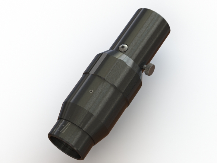
Focus Adjuster
This adjustable component is intended as a manual focusing device for a lens and nozzle assembly. By turning the notched ring, the tube with the engraved scale lowers or rises at a rate of 1mm per turn. 0.1mm increments are engraved on the outer sleeve. In total there is 20mm of movement, engraved as 10-5-0-5-10 with 1mm lines. A locking knob is provided to secure the focus setting.
The tube does not rotate as it slides: a pin at 90° to the locking knob rides in a slot to prevent rotation. This inturn prevents any beam wander from residual lens centring errors.
Both ends of the focusing unit have the thread to take the thread inserts.
Shutter Heads
The Shutter Head Unit is a critical component in laser systems, designed to control the path of the laser beam. It employs a rotary solenoid to flip a Supermax coated Silicon mirror in and out of the beam’s path.
When the shutter is closed, the beam is deflected onto a water-cooled beam dump, effectively stopping the beam from continuing along its original path. When the shutter is open, the beam passes straight through the unit, allowing it to proceed unimpeded.
The open position corresponds to the electrically activated state of the solenoid. This means that in the event of a power failure, the shutter will automatically close due to the force provided by a spring. This feature enhances the safety of the system by ensuring that the beam is blocked when there is no power.
The status of the shutter is indicated by LEDs on the shutter head: red for open and green for closed. The open and close positions are detected by opto-reflective switches, providing a reliable method of status detection.
Purpose and Functionality
Power is supplied to the Shutter Head Unit via a 9-pin D plug connector. The open/close status of the shutter can also be monitored through this connector. An optional Laser Shutter Controller, LSC01, can be used to supply power and monitor the status of the shutter.
The shutter is designed as a safety shutter, not intended for brief timing exposures. Using the LSC01, typical opening and closing times have been measured at 30 and 60 msec respectively. These times cannot be equalised due to the limitations of the solenoid. The clear aperture of the shutter is 19mm.
The beam dump is water-cooled via connectors (6/4 M6). The required water flow rate depends on the temperature rise (ΔT) and the laser power (P). For example, for a 10° rise in water temperature and a laser power of 500W, the flow rate should be 0.7 litres/min.
The shutter heads are equipped with retractable screw rings for mounting to a beam pipe. Before installing the shutter, it is important to ensure that the beam is centred to the beam pipe. Also, note that there is an input and output side to the shutter. Sending the beam in from the wrong side will cause it to hit the rear of the mirror mount.
The shutter is designed to operate in any orientation, providing flexibility in system design and setup.
Centering Cell
The centring cell has the two ‘thread insert’ connections on each side; one for the input and one for the output. By adjusting the 3 screws in the body side, it is possible to laterally adjust one with respect to the
other, either to precisely align the output to the beam or to introduce a deliberate offset.
Note that the screws need to be loosened on one side before those opposite can be screwed inwards. All 3 screws must be tightened once the adjustment is made.
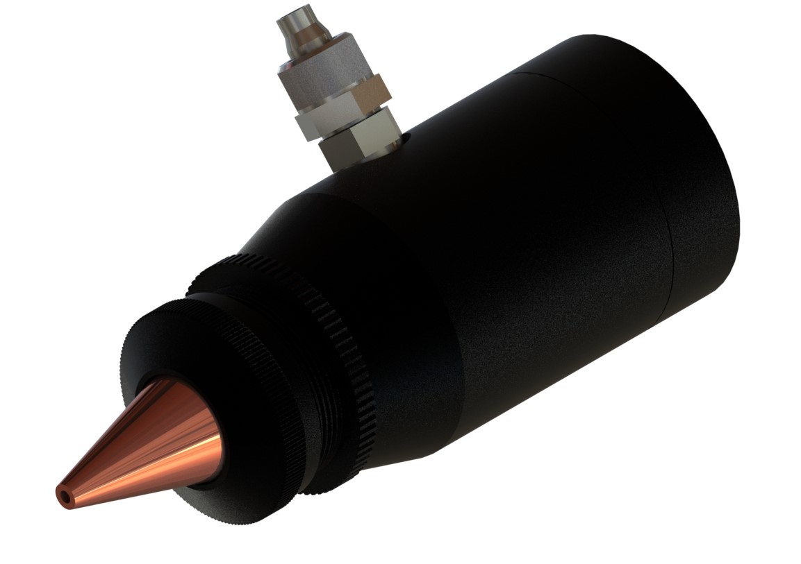
Lens Nozzles
The lens and nozzle assemblies come for 3 standard lens focal lengths: 38, 63 and 100mm. The lenses are mounted in a separate cell that is screwed into the nozzle section. The C-LN100 is a C-LN63 plus an extension piece and is shown above. The clear aperture inside the lens assembly is 17.5mm.
The copper nozzle is removed by unscrewing the cap while to adjust its distance from the lens (to give the correct stand-off, +/-3mm), unscrew the lock ring and screw the threaded tube in or out. Then tighten the lock ring.
The gas nozzle inlet allows a gas purge to be directed through the nozzle. With the standard lens, a pressure of up to 5 bar is possible. The inlet requires 6/4 tubing
Centering Cell
The centring cell has the two ‘thread insert’ connections on each side; one for the input and one for the output. By adjusting the 3 screws in the body side, it is possible to laterally adjust one with respect to the
other, either to precisely align the output to the beam or to introduce a deliberate offset.
Note that the screws need to be loosened on one side before those opposite can be screwed inwards. All 3 screws must be tightened once the adjustment is made.
Cross Wires
This useful item allows you to align the laser beam. It is a thread insert with a pair of copper wires and can therefore be screwed in at any location between parts to check for a central beam. Once the beam is aligned, replace it with a normal thread insert. A quick beam burn on card or viewing the beam on a mode plate will show the silhouette of the wires.
Make adjustments until the silhouette cross is central to the beam. You need to check the alignment a various places, working your way from the laser to the work piece. Any odd mode pattern may indicate that the beam is reflecting off the inside of a pipe or is being clipped somewhere.